How to Choose the Right Check Valve?
Choosing the right Check Valve is a practical decision, not a simple catalog search. In the field, a valve may look suitable yet fail under pressure, temperature, or contaminated fluid. A small pump station can reveal this quickly. Water hammer may shake the pipe, while a poorly matched disc may create constant pressure loss. These details matter.
The selection process begins with the system’s real operating conditions. Identify the fluid, flow direction, pressure range, temperature, pipe size, installation position, and required closing speed. Swing, lift, wafer, ball, and dual-plate designs each behave differently. A swing check valve may suit clean, steady flow. A spring-loaded model may close faster in a vertical line. That is not always enough, though. Viscous fluids, suspended particles, and pulsating pumps can change the result.
Look beyond the connection size. Review cracking pressure, reverse-flow performance, body materials, seal compatibility, maintenance access, and expected service life. Confirm the manufacturer’s test data and applicable industry standards, such as API, ASME, or ISO requirements. A qualified engineer should verify the final choice for critical systems. I have seen projects focus heavily on purchase price, then spend more on vibration and repairs. That lesson is easy to overlook.
There is no universal Check Valve. The best option balances safety, efficiency, durability, and total operating cost. This guide explains the key choices clearly, while recognizing that field conditions can challenge even a careful design.
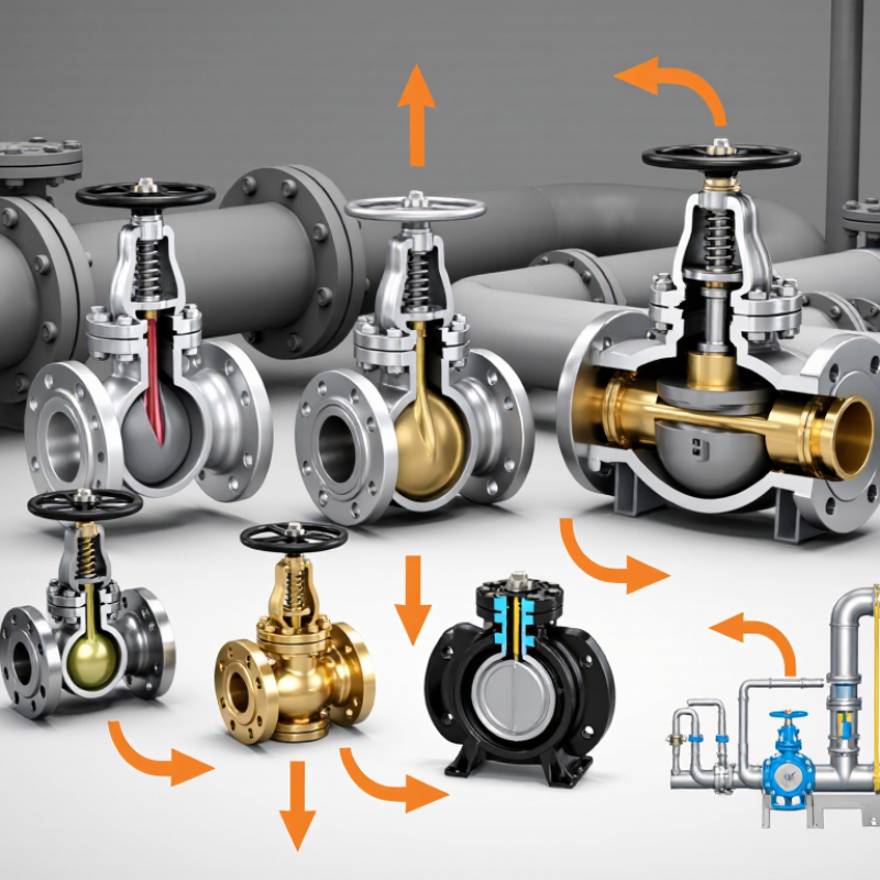
Define Flow Direction, Fluid Phase, and the Check Valve’s Operating Purpose
How to Choose the Right Check Valve?
Choosing a check valve starts with defining the real flow direction. The arrow must match the system’s normal operating path. A neat arrow on a drawing is not proof. During field inspections, installers sometimes discover reversed piping after commissioning. That mistake can cause vibration, leakage, or poor equipment protection. Check the pump outlet, pressure zones, and possible reverse-flow routes before selecting the valve.
Fluid phase matters just as much. Liquids, gases, and mixed-phase fluids behave differently inside the valve. A liquid system may need a valve that closes quickly without creating excessive water hammer. Gas service often demands careful attention to sealing, cracking pressure, and leakage control. Slurries can carry solids that damage delicate internal parts. I once saw a valve selected for clean water struggle with particles. The specification looked correct, but the service conditions were not.
Tips: Write down the fluid, temperature, pressure, flow rate, and pipe position. Then define the operating purpose. Is the valve protecting a pump, isolating a pressure zone, or preventing backflow into a process vessel? Consider startup, shutdown, and low-flow conditions. A valve that works well at full flow may chatter when demand falls. Review maintenance access too. The cheapest choice is not always the most reliable one, and field conditions often expose assumptions that calculations miss.
Match Pressure and Temperature Ratings from ASME Class 150 to Class 2500
How to Choose the Right Check Valve?
Pressure and temperature ratings must be matched together, not selected separately. ASME B16.34 pressure-temperature tables show why. For carbon steel valves at 100°F, Class 150 is rated around 285 psi, while Class 2500 reaches approximately 6,170 psi. These figures are not universal operating limits. Material grade, temperature, corrosion allowance, and valve design can change the result.
Temperature changes everything. A Class 600 valve may suit a cold water line, yet lose substantial allowable pressure in high-temperature steam service. Check the exact material table before ordering. API 6D also emphasizes documented pressure testing and traceable manufacturing records for pipeline valves. That evidence supports reliability, but it does not replace project-specific engineering review.
Check the process data.
Record normal, maximum, and upset pressure. Include startup surges and pump shutoff pressure. A valve rated just above normal pressure may still fail during transient events. Select the body class first, then verify the disc, seat, spring, and end connections. Flow direction matters too. Incorrect installation can cause chatter, vibration, and rapid seat wear.
I have seen specifications rely only on Class 150 labeling, which is an incomplete approach. The rating must match the real pressure-temperature combination. Sometimes, a higher class creates unnecessary cost and heavier maintenance. That trade-off deserves a second review.
Size the Valve Using Cv, Flow Velocity, and Cracking Pressure Data
How to Choose the Right Check Valve?
Size the valve using Cv, flow velocity, and cracking pressure data. Start with Cv, not the pipe diameter alone. For liquids, the common relation is Q = Cv√(ΔP/SG), using US customary units. Q is flow rate, ΔP is pressure loss, and SG is specific gravity. This calculation gives a useful first estimate, but it is not the whole answer.
Crane Technical Paper No. 410 explains that friction loss rises approximately with the square of velocity. A small increase in velocity can therefore create a sharp pressure penalty. Check the manufacturer’s tested pressure-drop curve at the actual flow rate. The Hydraulic Institute’s valve and piping guidance also supports evaluating operating velocity, transient conditions, and system resistance together. For water systems, many engineers begin reviewing velocity near 2–3 m/s, then adjust for noise, erosion, and water hammer risk. That range is not universal. Gas, slurry, and high-temperature service need different limits. Cracking pressure matters too. Select the lowest pressure that reliably opens the valve, while preventing reverse flow during low-flow operation. A valve with excessive cracking pressure may remain closed when the pump barely starts.
Tips: Record minimum, normal, and maximum flow. Compare Cv at each point. Verify pressure loss, not just catalog size. I still recheck the calculation in the field; fittings, installation angle, and pulsation can make a neat spreadsheet imperfect. References: Crane TP-410, Flow of Fluids; Hydraulic Institute engineering guidance; U.S. Department of Energy, Improving Pumping System Performance: A Sourcebook.
How to Choose the Right Check Valve? - Size the Valve Using Cv, Flow Velocity, and Cracking Pressure Data
Indicative water-service sizing worksheet. Values are calculated using specific gravity = 1.00 and a screening pressure-loss allowance of 0.5 psi (0.034 bar). | Service Point | Nominal Pipe Size | Reference Internal Diameter | Design Flow | Flow Velocity | Velocity Assessment | Screening Pressure-Loss Allowance | Minimum Calculated Cv | Cracking Pressure Target | Selection Guidance |
| Small instrument-water branch | DN15 / 1/2 in | 15.8 mm | 10 L/min
(2.64 US gpm) | 0.85 m/s | Within typical range | 0.5 psi
(0.034 bar) | 3.74 | ≤ 0.03 bar
(0.44 psi) | Use a compact valve with low cracking pressure and a rated Cv of at least 3.74. |
| Utility-water branch | DN25 / 1 in | 26.6 mm | 25 L/min
(6.60 US gpm) | 0.75 m/s | Within typical range | 0.5 psi
(0.034 bar) | 9.34 | ≤ 0.05 bar
(0.73 psi) | Select a valve whose published flow curve confirms Cv ≥ 9.34 at the required opening condition. |
| General process-water line | DN40 / 1 1/2 in | 40.9 mm | 60 L/min
(15.85 US gpm) | 0.76 m/s | Within typical range | 0.5 psi
(0.034 bar) | 22.40 | ≤ 0.05 bar
(0.73 psi) | Choose the smallest suitable valve that meets the flow, pressure, temperature, and installation requirements. |
| Cooling-water header branch | DN50 / 2 in | 52.5 mm | 100 L/min
(26.42 US gpm) | 0.77 m/s | Within typical range | 0.5 psi
(0.034 bar) | 37.36 | ≤ 0.10 bar
(1.45 psi) | Confirm that the valve does not create excessive pressure loss at normal and maximum flow. |
| Large utility-water line | DN80 / 3 in | 77.9 mm | 250 L/min
(66.04 US gpm) | 0.87 m/s | Within typical range | 0.5 psi
(0.034 bar) | 93.40 | ≤ 0.10 bar
(1.45 psi) | Review valve-disc stability, installation orientation, surge risk, and the complete manufacturer flow curve. |
| High-capacity cooling-water line | DN100 / 4 in | 102.3 mm | 450 L/min
(118.88 US gpm) | 0.91 m/s | Within typical range | 0.5 psi
(0.034 bar) | 168.13 | ≤ 0.20 bar
(2.90 psi) | Prioritize low head loss, non-slam closing behavior, and compatibility with the maximum reverse pressure. |
Calculation basis:
Flow velocity = volumetric flow ÷ pipe cross-sectional area.
For water service, Cv = Qgpm × √(SG ÷ ΔPpsi), so the minimum screening Cv values above use SG = 1.00 and ΔP = 0.5 psi.
Cracking pressure is the upstream pressure required to begin opening the valve. The stated targets are design limits, not product ratings; final selection must be verified against the valve’s certified Cv curve, pressure class, temperature rating, fluid compatibility, installation orientation, and water-hammer requirements.
Select Body and Trim Materials for Corrosion and Temperature Resistance
How to Choose the Right Check Valve?
Select Body and Trim Materials for Corrosion and Temperature Resistance
Material selection starts with the fluid, not the valve price. The NACE IMPACT study estimated global corrosion costs at 2.5 trillion US dollars annually, equal to 3.4% of global GDP. That figure shows why corrosion control deserves engineering attention. A stainless-steel body may resist clean water, yet chloride-rich water can cause pitting. Seawater, sour gas, acids, and caustic fluids require different solutions. Confirm concentration, velocity, pressure, and contaminants before choosing the body.
Temperature changes the decision. ASME B16.34 pressure-temperature ratings show that allowable pressure commonly decreases as temperature rises. Trim materials must also tolerate impact, erosion, and repeated cycling. Hardened stainless trim can suit abrasive service, while nickel-based alloys may perform better in severe chemical environments. Soft seats provide tight shutoff, but some elastomers lose elasticity near their temperature limits. Always check the manufacturer’s verified temperature curve, not a general catalog range.
A practical review includes the minimum startup temperature and the maximum upset temperature. Do not size only for normal operation. I have seen material schedules overlook short cleaning cycles, then fail early. That mistake is easy to repeat. Cross-check the selection against ISO 15156 for sour-service exposure and documented corrosion data from testing. If fluid chemistry is uncertain, laboratory compatibility testing is often cheaper than replacing a seized valve.
Verify API 598, ISO 5208, Installation, Leakage, and Maintenance Requirements
Choosing the right check valve starts with the service, not the catalog size. Confirm the fluid, pressure, temperature, flow direction, and expected cycling frequency. A valve suitable for clean water may fail quickly in abrasive slurry. Field inspection should also consider pipe vibration and possible water hammer.
Ask for test documentation based on API 598 or ISO 5208. These standards define pressure testing and leakage acceptance, but they are not interchangeable by assumption. Check the specified test pressure, duration, seat leakage rate, and test medium. A certificate without clear acceptance criteria is weak evidence. Small details matter.
Installation can decide performance. Match the valve arrow with actual flow direction. Keep the line clean before fitting the valve. Remove welding beads, scale, and packing debris. Provide enough straight pipe and support to prevent body stress. After commissioning, record pressure, temperature, noise, and any reverse flow. Maintenance should include periodic leakage checks, bolt inspection, and review of operating records. Replace damaged seals with compatible materials. Do not wait for visible failure.
A checklist helps.
It can still miss problems. In practice, maintenance intervals often reflect habit rather than real duty. Reassess them when flow conditions change, when the valve cycles unusually often, or when shutdown testing reveals unstable leakage. Reliable selection combines standard-based testing with installation evidence and honest operating data.
How to Choose the Right Check Valve?
API 598 and ISO 5208 mainly verify pressure testing and leakage performance; installation and maintenance must be controlled through project and manufacturer procedures.
Interpretation: a value of 1 indicates that the topic is directly addressed by the referenced test standard, while 0 indicates that it is not the standard’s primary scope. API 598 defines valve pressure-test requirements, including shell, backseat, and closure testing. ISO 5208 defines pressure-testing procedures and leakage-rate classifications. Neither standard replaces site-specific installation, inspection, or maintenance instructions.