
Financing

If you are interested in financing to fund your Bay-Lynx purchase, we recommend that you connect with Easylease Corp., a Canadian-based leasing and finance company that offers premier equipment leasing and financial services. They are focused on making it easier than ever before for companies to overcome cash flow and resource constraints to acquire the assets they need to grow their business.

Leasing through Easylease Corp. can offer several benefits:

  • Conserve Cash Leasing
  • 100% Financing
  • No Pre-Payment of Taxes
  • Preserve Lines of Credit
  • Potential Income Tax Benefits
  • Pay as You Profit
  • Match Revenue with Expenditures
  • Simple, Convenient Process
  • Tailored Payments

Click here for your Canadian instant lease quote >>

For US customers, Click here for your instant lease application >>

How to Choose OPGW for Transmission Lines in 2026?

Choosing OPGW for transmission lines in 2026 requires more than comparing fiber counts and prices. Grid operators now face higher power flows, severe weather, aging towers, and stricter reliability expectations. Opgw In Transmission Line applications must provide dependable communication while performing as an overhead ground wire. These roles create competing demands. A heavier cable may improve mechanical strength, yet increase tower loading and installation difficulty.

This guide examines practical selection factors used by engineers and experienced line contractors. They include fault-current capacity, short-circuit duration, sag-tension behavior, fiber type, fiber count, cable diameter, and installation equipment. Environmental conditions also matter. Coastal salt, mountain ice, desert heat, and industrial pollution can affect long-term performance. The correct design should match tower geometry, span length, wind pressure, and existing grounding arrangements. Small calculation errors can become expensive field problems.

Standards and verified test data deserve close attention. Buyers should review manufacturer quality records, routine test results, type-test evidence, and compliance with applicable IEC, IEEE, and local utility requirements. Factory claims alone are not enough. An impressive datasheet may hide weak installation support or limited repair experience. This guide also considers joint boxes, fittings, emergency replacement plans, and future network capacity. One limitation remains: no universal OPGW specification suits every corridor. Local surveys and detailed engineering are still essential. A careful decision balances safety, communication performance, lifecycle cost, and constructability rather than chasing the lowest quotation.
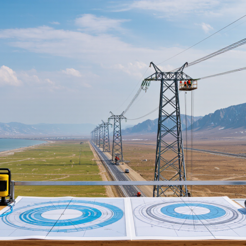
How to Choose OPGW for Transmission Lines in 2026?

OPGW Basics: Fiber Counts, 1310/1550 nm Windows, and IEC 60794 Standards

Choosing OPGW in 2026 starts with the fiber count, not the cable diameter. In a substation survey, I check protection channels, control links, maintenance access, and future expansion. Eight fibers may serve a small route, while 24 or 48 fibers offer practical spare capacity. More fibers also affect tube space, weight, and installation tension.

The optical window matters too. The 1310 nm window usually offers low chromatic dispersion and suits shorter transmission paths. The 1550 nm window provides lower attenuation, making it useful for longer routes and higher optical budgets. However, real performance depends on fiber design, splice loss, connector quality, and bending conditions. A neat calculation can still mislead. Field records are essential.

1310 nm
Low chromatic dispersion

1550 nm
Lower attenuation

IEC 60794 provides a framework for optical fiber cable testing. When reviewing an OPGW datasheet, verify mechanical, environmental, and optical test requirements. Pay attention to tensile strength, crush resistance, temperature cycling, water penetration, and vibration. The cable must also match the line’s fault-current and sag-tension calculations. I would not accept a certificate without checking its test method and sample condition. That step is often overlooked.

Project engineers should compare the stated fiber count with actual network architecture. They should also confirm whether the 1310 nm or 1550 nm loss budget fits the complete link. Standards help, but site evidence decides.

Assess Line Conditions: Span Length, Ice Loads, Wind Speed, and Operating Temperature

How to Choose OPGW for Transmission Lines in 2026?

Assess the line before selecting an OPGW design. Span length directly affects sag, tension, and installation clearance. A 500-meter crossing needs stronger mechanical performance than a 120-meter roadside span. Check tower spacing, attachment height, and conductor clearance under maximum sag. Ice loads also matter. A thin ice layer can add surprising weight to the cable. Use local design records, not assumptions. Wind pressure increases vibration and mechanical stress, especially on exposed ridges. Review the site’s maximum wind speed, prevailing direction, and combined ice-wind conditions.

Operating temperature requires equal attention. High temperatures can increase sag and reduce clearance near roads or buildings. Low temperatures may raise tension beyond expected levels. Select an OPGW with suitable thermal performance, rated breaking strength, and short-circuit capacity. Confirm these values against the project’s protection settings and fault duration. Installation conditions deserve practical attention too. Pulling tension, bending radius, and stringing equipment can influence final performance. A specification may look correct on paper but fail during a difficult installation.

Tips: Request verified weather data and a complete line profile. Calculate sag under normal, ice, wind, and emergency conditions. Do not size from span length alone. A preliminary choice may be wrong after tower loading is checked. Revisit it. Independent engineering review can expose overlooked clearance, temperature, or grounding risks. Keep the calculation record for future maintenance decisions.

Match Mechanical Ratings: RTS, Sag-Tension Limits, and IEEE 1138 Requirements

Choosing OPGW for a 2026 transmission project requires more than matching fiber count. Mechanical performance must fit the line’s actual loading conditions. Start with Rated Tensile Strength (RTS), then compare it with installation tension, everyday operating tension, and emergency loads. A higher RTS is not automatically better if the structure cannot support the added weight.

Sag-tension calculations should include span length, conductor temperature, wind pressure, ice, elevation, and long-term creep. Check clearances at the hottest and most heavily loaded conditions. On site, small differences matter. A few centimeters of extra sag can reduce clearance near roads, towers, or crossing lines. I have seen designs pass a basic review but fail when construction tension was overlooked.

IEEE 1138 provides a recognized framework for evaluating OPGW construction, testing, and performance. Request verified mechanical data, including breaking strength, elastic modulus, thermal expansion, bending limits, and allowable installation tension. Compare these values with the project’s stringing method and hardware. Numbers can deceive. A cable may meet its listed RTS but still perform poorly with unsuitable clamps or excessive pulling tension. Review the complete system, not only the cable table. One imperfect assumption in the loading model can affect safety, reliability, and maintenance costs for decades.

How to Choose OPGW for Transmission Lines in 2026?

Match mechanical ratings: RTS, sag-tension limits, and IEEE 1138 requirements

The chart uses representative OPGW screening points with rated tensile strength (RTS) values of 60–120 kN. The everyday-tension screening value is shown at 18% of RTS, a commonly used project design criterion; actual sag-tension limits depend on span length, temperature, wind, ice, installation tension, creep, and utility specifications. IEEE 1138 defines qualification and testing requirements for OPGW, but it does not prescribe one universal RTS value.

Select Fiber Design: G.652.D, G.655, Loss Below 0.35 dB/km, and Capacity

Choosing OPGW in 2026 starts with the fiber design, not only the cable diameter. G.652.D is a practical option for standard transmission links and broad compatibility. It performs well across common communication windows. G.655 can reduce nonlinear effects on longer, densely loaded routes. The better choice depends on span length, wavelength plan, and network upgrades.

Target attenuation below 0.35 dB/km at the operating wavelength. However, this figure alone does not guarantee a reliable link. Field connectors, splices, bends, and aging add real losses. During project reviews, I compare factory test records with calculated link budgets. I also check whether the fiber count supports future protection channels, monitoring, and higher capacity. More fibers help, but they can increase cable size, weight, and installation stress. That trade-off is easy to underestimate.

Tips: Request test data at the actual operating wavelengths, not only at one reference point. Confirm chromatic dispersion and polarization performance for long routes. Leave sensible capacity for future traffic. A perfect calculation can still fail after poor splicing. I have seen designs meet the fiber specification yet miss the system target because installation losses were treated as negligible. Review those assumptions before approval.

Verify 2026 Compliance: Fault Current, Short-Circuit Heating, and Installation Tests

How to Choose OPGW for Transmission Lines in 2026?

OPGW selection begins with verified fault-current data, not only fiber capacity. Obtain the utility’s maximum symmetrical and asymmetrical short-circuit values. Check clearing time, fault duration, and tower grounding conditions. The cable must withstand thermal stress without losing mechanical strength. Use the latest project specifications and applicable IEC or IEEE requirements. However, “2026 compliance” is not one universal certificate. Confirm the required editions with the transmission owner and local authority.

Tips: Request a manufacturer’s short-circuit calculation. Compare calculated temperature with the cable’s allowable limit. Ask for test evidence, not general claims. Review fiber attenuation, tensile strength, sag, and lightning performance together. Small omissions matter.

Installation can damage a suitable OPGW. Before stringing, inspect drums, sheaths, fittings, and fiber records. Control pulling tension and bending radius at every structure. After installation, perform continuity, attenuation, optical time-domain, and grounding checks. Record results by span or joint. Field teams should also inspect vibration dampers and bonding connections. I have found that incomplete test records create more uncertainty than failed measurements. That is not ideal, but it is common. A second review is worthwhile. Use the final data to confirm electrical performance, optical integrity, and safe operation under credible fault conditions.

How to Choose OPGW for Transmission Lines in 2026? – Verify 2026 Compliance: Fault Current, Short-Circuit Heating, and Installation Tests

Selection / Verification Dimension Typical 2026 Design Scenario Representative Data Acceptance or Design Check Applicable Reference
Fault current and duration Regional transmission corridor with moderate fault duty 16 kA for 0.5 s; I²t = 64 MA²·s The OPGW supplier’s certified short-circuit rating shall be at least 16 kA for 0.5 s at the specified initial conductor temperature. IEC 60794-4-10; IEEE 1138
Fault current and duration High-capacity substation interconnection 25 kA for 0.5 s; I²t = 156.25 MA²·s Select an OPGW with a tested rating of at least 25 kA for 0.5 s; do not substitute a rating based only on the nominal cable diameter. IEC 60794-4-10; IEEE 1138
Fault current and duration Extra-high-voltage line with prolonged clearing time 31.5 kA for 1.0 s; I²t = 992.25 MA²·s Require a project-specific thermal calculation and a type-test certificate matching the conductor materials, metallic cross-section, current, duration, and starting temperature. IEC 60794-4-10; IEEE 1138
Short-circuit heating Adiabatic first-pass thermal screening Use I²t and the effective metallic area; include conductor resistivity, temperature coefficient, heat capacity, and allowable final temperature. The calculated final temperature shall remain within the qualified limit for the actual OPGW construction. A generic aluminium or steel formula shall not replace the manufacturer’s tested rating. IEC 60794-4-10; IEEE 1138
Metallic cross-section Thermal and mechanical selection Common practical screening range: approximately 70–120 mm² effective metallic area, subject to design confirmation. Confirm the actual aluminium-alloy, aluminium-clad steel, or steel strand area and DC resistance at 20 °C before approving the design. IEC 60794-4-10; IEC 60228 principles for conductor resistance
Rated tensile strength Long spans, high wind, or heavy ice loading Typical project screening values: 70–120 kN minimum breaking load, depending on span and loading. Rated tensile strength shall exceed the maximum calculated everyday tension and the governing installation or extreme-weather load with the project safety factor. IEC 60794-4-10; IEC 60826; local overhead-line code
Maximum installation tension Stringing over energized or congested lines Use the cable-specific installation limit; a common planning range is 15–25% of rated tensile strength. The approved stringing chart shall define maximum tension, allowable bending radius, sag, pulling speed, and sheave diameter. IEC 60794-1-2; manufacturer installation specification
Fiber capacity Protection, control, SCADA, and future communication expansion 24, 48, or 96 single-mode fibers; select spare capacity after operational and future-growth requirements are included. Verify fiber type, attenuation, chromatic dispersion, polarization mode dispersion, splice compatibility, and reserve fibers. ITU-T G.652; IEC 60794-4-10
Optical attenuation Standard single-mode transmission at 1310 nm and 1550 nm Typical maximum design values: 0.35 dB/km at 1310 nm and 0.22 dB/km at 1550 nm, subject to the specified fiber class. Measure attenuation on each fiber before installation and after installation; compare results with the approved optical budget. ITU-T G.652; IEC 60794-1-2
Temperature range Seasonal outdoor operation with fault heating Typical operating design range: approximately −40 °C to +70 °C; short-circuit temperature is a separate verified rating. Check sag, clearance, optical attenuation, sheath condition, and hardware compatibility at minimum, maximum, and fault-heated temperatures. IEC 60794-4-10; IEC 60826
Factory acceptance tests Pre-shipment quality verification Dimensional inspection, fiber attenuation, continuity, DC resistance, tensile verification, and drum-length inspection. Require test records traceable to the production lot and cable drum; reject drums with unexplained optical loss or physical damage. IEC 60794-1-2; IEC 60794-4-10
Installation inspection During stringing, sagging, and dead-end installation Record pulling tension, bending events, minimum sheave diameter, cable twist, visible damage, sag, and clearance. No kinks, crushed sections, strand displacement, excessive twist, sheath damage, or installation tension above the approved limit. IEC 60794-1-2; approved construction method statement
Post-installation optical tests Commissioning after splicing and hardware installation OTDR trace from both ends, insertion-loss measurement, continuity test, fiber identification, and splice-loss verification. Results shall meet the approved link budget and show no unexplained reflective event, excessive splice loss, or localized attenuation increase. IEC 60794-1-2; ITU-T G.652
Grounding and bonding Shield-wire replacement and substation entry Bonding points, downleads, clamps, and termination hardware shall be coordinated with the station grounding grid. Verify continuity, hardware torque, corrosion protection, and current-sharing paths; confirm compatibility with the calculated fault current. IEEE 80; IEC 60794-4-10; project grounding standard
Engineering note: The numerical scenarios are representative screening cases, not universal ratings. Final OPGW selection shall use the actual fault current, clearing time, initial conductor temperature, metallic construction, span loading, installation method, optical link budget, and applicable national requirements. A certified short-circuit type test or validated calculation for the exact cable construction should be obtained before procurement.